





Vector Control Inverter INVT series GD20-EU
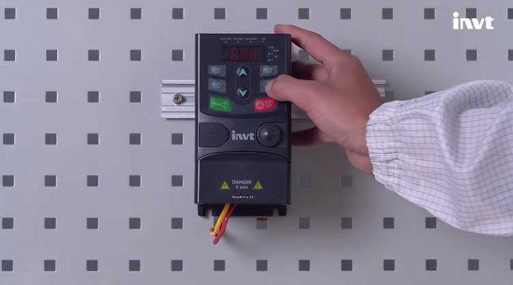
INVT is a large industrial group, manufacturer of inverters and brushless drives, the GD20-EU series includes small vector inverters for general use with an extensive range, up to 110KW.
The presence of the integrated EMC filter from 4kW (plug-in option for sizes up to 2.2kW), the standard braking chopper, up to a power of 37kW included makes it one of the most complete inverters.
Parameter Settings
On this page, we provide only the immediate indications for setting the parameters; for complete information, please refer to the user manual. The inverter is standard equipped with a keyboard with a display for access to all configuration parameters; an optional remote keyboard is also available that includes the parameter copy function.
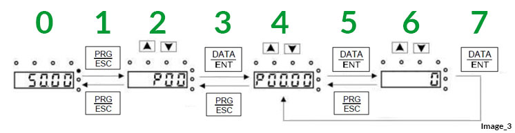
Below are the steps to program the parameters from the keyboard:
0 Main menu.
1 Group display: Pressing the [PRG/ESC] key displays the group on the screen.
2 Group selection: The [Up] and [Dw] keys allow group selection. Pressing the [PRG/ESC] key returns to the main menu (Step 0).
3 Parameter display: Pressing the [DATA/ENT] key displays the group and parameter on the screen.
4 Parameter selection: The [Up] and [Dw] keys allow parameter selection. Pressing the [PRG/ESC] key returns to group selection (Step 2).
5 Parameter value: Pressing the [DATA/ENT] key displays the parameter value on the screen.
6 Parameter setting: If the value is blinking, it can be set using the [Up] and [Dw] keys. Pressing the [PRG/ESC] key returns to parameter selection (Step 4) without changing the value.
7 Value storage: Pressing the [DATA/ENT] key permanently stores the defined value, returning to parameter selection (Step 4).
Below is a table with all the inverter parameters divided by groups, with the default value indicated for each parameter.
To set all inverter parameters to default, set P00.18=1.
P00, Basic functions
P00.00 | Speed control mode | 2
P00.01 | Run command channel | 0
P00.02 | Reserved | 0
P00.03 | Max output frequency | 50.00
P00.04 | Upper limit of running frequency | 50.00
P00.05 | Upper limit of running frequency | 0.00
P00.06 | A frequency command selection | 2
P00.07 | B frequency command selection | 0
P00.08 | B frequency command reference object | 0
P00.09 | Combination mode of the setting source | 0: A
P00.10 | Keypad set frequency | 50.00
P00.11 | Acc time 1 | 10.0
P00.12 | Dec time 1 | 10.0
P00.13 | Running direction selection | 0
P00.14 | Carrier frequency setting | 8.0
P00.15 | Motor parameter autotuning | 0
P00.16 | AVR function selection | 1
P00.17 | Reserved | ****
P00.18 | Function parameter restoration | 0
P01, Start/Stop motor
P01.00 | Start mode | 0
P01.01 | Starting frequency of direct start-up | 0.50
P01.02 | Hold time of the starting frequency | 0.0
P01.03 | Braking current before starting | 0.0
P01.04 | Braking time before starting | 0.0
P01.05 | Acc/dec mode selection | 0
P01.06 | Acc time of the starting section of S curve | 0.1
P01.07 | Dec time of the ending section of S curve | 0.1
P01.08 | Stop mode selection | 0
P01.09 | Starting frequency of DC braking | 0.00
P01.10 | Stop brake waiting time | 0.0
P01.11 | Stop DC brake current | 0.0
P01.12 | Stop DC brake time | 0.0
P01.13 | Deadzone time of FWD/REV rotation | 0.0
P01.14 | FWD/REV rotation switching mode | 0
P01.15 | Stop speed | 0.50
P01.16 | Stop speed detection mode | 1
P01.17 | Feedback speed detection time | 5.0
P01.18 | Power-on terminal running protection selection | 0
P01.19 | Action when running frequency is lower than the lower limit | 0
P01.20 | Wake up from sleep delay time | 0.0
P01.21 | Restart after power off | 0
P01.22 | The waiting time of restart after power off | 1.0
P01.23 | Start delay time | 0.0
P01.24 | Stop speed delay time | 0.0
P01.25 | 0Hz output selection | 0: No voltage output
P02, Motor configuration
P02.00 | Reserved | ****
P02.01 | Rated power of asynchronous motor 1 | 0.4
P02.02 | Rated frequency of asynchronous motor 1 | 50.00
P02.03 | Rated speed of asynchronous motor 1 | 1400
P02.04 | Rated voltage of asynchronous motor 1 | 230
P02.05 | Rated current of asynchronous motor 1 | 2.4
P02.06 | Stator resistance of asynchronous motor 1 | 3349
P02.07 | Rotor resistance of asynchronous motor 1 | 3659
P02.08 | Leakage inductance of asynchronous motor 1 | 23.6
P02.09 | Mutual inductance of asynchronous motor 1 | 209.3
P02.10 | No-load current of asynchronous motor 1 | 2.0
P02.11 | Magnetic saturation coefficient 1 of asynchronous motor 1 core | 80.0
P02.12 | Magnetic saturation coefficient 2 of asynchronous motor 1 core | 68.0
P02.13 | Magnetic saturation coefficient 3 of asynchronous motor 1 core | 57.0
P02.14 | Magnetic saturation coefficient 4 of asynchronous motor 1 core | 40.0
P02.15 | Reserved | ****
P02.16 | Reserved | ****
P02.17 | Reserved | ****
P02.18 | Reserved | ****
P02.19 | Reserved | ****
P02.20 | Reserved | ****
P02.21 | Reserved | ****
P02.22 | Reserved | ****
P02.23 | Reserved | ****
P02.24 | Reserved | ****
P02.25 | Reserved | ****
P02.26 | Overload protection selection of motor 1 | 2
P02.27 | Overload protection coefficient of motor 1 | 100.0
P02.28 | Reserved | ****
P02.29 | Reserved | ****
P03, Vector control
P03.00 | Speed loop proportional gain 1 | 20.0
P03.01 | Speed loop integral time 1 | 200
P03.02 | Switching low point frequency | 5.00
P03.03 | Speed loop proportional gain 2 | 20.0
P03.04 | Speed loop integral time 2 | 200
P03.05 | Switching high point frequency | 10.00
P03.06 | Speed loop output filter | 0
P03.07 | Compensation coefficient of vector control slip (electromotion) | 100
P03.08 | Compensation coefficient of vector control slip (power generation) | 100
P03.09 | Current loop proportional coefficient P | 1000
P03.10 | Current loop integral coefficient I | 1000
P03.11 | Torque setting mode | 0
P03.12 | Keypad setting torque | 50.0
P03.13 | Torque reference filter time | 100
P03.14 | Setting source of forward rotation upper-limit frequency in torque control | 0
P03.15 | Setting source of reverse rotation upper-limit frequency in torque control | 0
P03.16 | Torque control forward rotation upper-limit frequency keypad limit value | 50.00
P03.17 | Torque control reverse rotation upper-limit frequency keypad limit value | 50.00
P03.18 | Upper-limit setting source of electromotion torque | 0
P03.19 | Upper-limit setting source of brake torque | 0
P03.20 | Electromotion torque upper-limit set by keypad | 180.0
P03.21 | Brake torque upper-limit set by keypad | 180.0
P03.22 | Flux-weakening coefficient in constant power zone | 0.3
P03.23 | Min flux-weakening point in constant power zone | 20
P03.24 | Max voltage limit | 100.0
P03.25 | Pre-exciting time | 300
P03.26 | Flux-weakening proportional gain | 1200
P03.27 | Speed display selection of vector control | 0
P03.28 | Reserved | ****
P03.29 | Reserved | ****
P04, V/F Control
P04.00 | V/F curve setting of motor 1 | 0
P04.01 | Torque boost of motor 1 | 0.0
P04.02 | Torque boost end of motor 1 | 20.0
P04.03 | V/F frequency point 1 of motor 1 | 0.00
P04.04 | V/F voltage point 1 of motor 1 | 0.0
P04.05 | V/F frequency point 2 of motor 1 | 0.00
P04.06 | V/F voltage point 2 of motor 1 | 0.0
P04.07 | V/F frequency point 3 of motor 1 | 0.00
P04.08 | V/F voltage point 3 of motor 1 | 0.0
P04.09 | V/F slip compensation gain of motor 1 | 100.0
P04.10 | Low frequency vibration control factor of motor 1 | 10
P04.11 | High frequency vibration control factor of motor 1 | 10
P04.12 | Vibration control threshold of motor 1 | 30.00
P04.13 | Reserved | ****
P04.14 | Reserved | ****
P04.15 | Reserved | ****
P04.16 | Reserved | ****
P04.17 | Reserved | ****
P04.18 | Reserved | ****
P04.19 | Reserved | ****
P04.20 | Reserved | ****
P04.21 | Reserved | ****
P04.22 | Reserved | ****
P04.23 | Reserved | ****
P04.24 | Reserved | ****
P04.25 | Reserved | ****
P04.26 | Reserved | ****
P04.27 | Voltage Setting channel selection | 0
P04.28 | Voltage value set via keypad | 100.0
P04.29 | Voltage increase time | 5.0
P04.30 | Voltage decrease time | 5.0
P04.31 | Output maximum voltage | 100.0
P04.32 | Output minimum voltage | 0.0
P04.33 | Reserved | ****
P04.34 | Reserved | ****
P04.35 | Reserved | ****
P05, Input configuration
P05.00 | HDI input type selection | 0
P05.01 | S1 terminal function selection | 1
P05.02 | S2 terminal function selection | 4
P05.03 | S3 terminal function selection | 7
P05.04 | S4 terminal function selection | 0
P05.05 | Reserved | ****
P05.06 | Reserved | ****
P05.07 | Reserved | ****
P05.08 | Reserved | ****
P05.09 | HDI terminal function selection | 0
P05.10 | Input terminal polarity selection | 0x0000
P05.11 | Digital filter time | 10
P05.12 | Virtual terminal setting | 0x0000
P05.13 | Terminal control running mode | 0
P05.14 | S1 terminal close delay time | 0
P05.15 | S1 terminal open delay time | 0
P05.16 | S2 terminal close delay time | 0
P05.17 | S2 terminal open delay time | 0
P05.18 | S3 terminal close delay time | 0
P05.19 | S3 terminal open delay time | 0
P05.20 | S4 terminal close delay time | 0
P05.21 | S4 terminal open delay time | 0
P05.22 | S5 terminal close delay time | 0
P05.23 | S5 terminal open delay time | 0
P05.24 | S6 terminal close delay time | 0
P05.25 | S6 terminal open delay time | 0
P05.26 | S7 terminal close delay time | 0
P05.27 | S7 terminal open delay time | 0
P05.28 | S8 terminal close delay time | 0
P05.29 | S8 terminal open delay time | 0
P05.30 | HDI terminal close delay time | 0
P05.31 | HDI terminal open delay time | 0
P05.32 | Lower limit value of AI1 | 0.00
P05.33 | Corresponding setting of AI1 lower limit | 0.0
P05.34 | Upper limit value of AI1 | 10.00
P05.35 | Corresponding setting of AI1 upper limit | 100.0
P05.36 | AI1 input filter time | 100
P05.37 | Lower limit value of AI2 | 0.00
P05.38 | Corresponding setting of AI2 lower limit | 0.0
P05.39 | Upper limit value of AI2 | 10.00
P05.40 | Corresponding setting of AI2 upper limit | 100.0
P05.41 | AI2 input filter time | 100
P05.42 | Lower limit value of AI3 | -10.00
P05.43 | Corresponding setting of AI3 lower limit | -100.0
P05.44 | Intermediate value of AI3 | 0.00
P05.45 | Corresponding setting of AI3 intermediate value | 0.0
P05.46 | Upper limit value of AI3 | 10.00
P05.47 | Corresponding setting of AI3 upper limit | 100.0
P05.48 | AI3 input filter time | 100
P05.49 | Reserved | ****
P05.50 | Lower limit frequency of HDI1 | 0.00
P05.51 | Corresponding setting of HDI1 lower limit frequency | 0.0
P05.52 | Upper limit frequency of HDI1 | 500.00
P05.53 | Corresponding setting of HDI1 upper limit frequency | 100.0
P05.54 | HDI1 frequency input filter time | 100
P06, Output configuration
P06.00 | Reserved | ****
P06.01 | Y1 output selection | 27
P06.02 | HDO output | 0
P06.03 | Relay RO1 output selection | 1
P06.04 | Relay RO2 output selection | 5
P06.05 | Output terminal polarity selection | 0x0000
P06.06 | Y1 switch-on delay time | 0
P06.07 | Y1 switch-off delay time | 0
P06.08 | Reserved | ****
P06.09 | Reserved | ****
P06.10 | Relay RO1 delay time | 0
P06.11 | Relay RO1 switch-off delay time | 0
P06.12 | Relay RO1 delay time | 0
P06.13 | Relay RO2 switch-off delay time | 0
P06.14 | AO1 output selection | 0
P06.15 | AO2 output selection | 0
P06.16 | Reserved | ****
P06.17 | Lower limit of AO1 output | 0.0
P06.18 | Corresponding AO1 output of lower limit | 0.00
P06.19 | Upper limit of AO1 output | 100.0
P06.20 | Corresponding AO1 output of upper limit | 10.00
P06.21 | Output filter time of AO1 | 0
P06.22 | Lower limit of AO2 output | 0.0
P06.23 | Corresponding AO2 output of lower limit | 0.00
P06.24 | Upper limit of AO2 output | 100.0
P06.25 | Corresponding AO2 output of upper limit | 10.00
P06.26 | AO2 output filter time | 0
P06.27 | Reserved | ****
P06.28 | Reserved | ****
P06.29 | Reserved | ****
P06.30 | Reserved | ****
P06.31 | Reserved | ****
P07, HMI configuration
P07.00 | User password | ****
P07.01 | Function parameter copy | 0
P07.02 | QUICK/JOG key function selection | 0x0001
P07.03 | QUICK key running command channel switching sequence selection | 0
P07.04 | STOP/RST key stop function selection | 0
P07.05 | Parameter selection 1 of running state display | 0x03FF
P07.06 | Parameter selection 1 of running state display | 0x0000
P07.07 | Parameter selection of stop state display | 0x00FF
P07.08 | Frequency display coefficient | 1.00
P07.09 | Speed display coefficient | 100.0
P07.10 | Linear speed display coefficient | 1.0
P07.11 | Rectifier bridge module temperature | 35.9
P07.12 | Inverter module temperature | 35.9
P07.13 | Control board software version | 101.12
P07.14 | Accumulated running time | 8
P07.15 | High bit of inverter power consumption | 0
P07.16 | Low bit of inverter power consumption | 0.0
P07.17 | Reserved | ****
P07.18 | Rated inverter power | 0.4
P07.19 | Rated inverter voltage | 230
P07.20 | Rated inverter current | 2.5
P07.21 | Factory barcode 1 | 0x0006
P07.22 | Factory barcode 2 | 0x000F
P07.23 | Factory barcode 3 | 0x0197
P07.24 | Factory barcode 4 | 0x0002
P07.25 | Factory barcode 5 | 0x3213
P07.26 | Factory barcode 6 | 0x1928
P07.27 | Present fault type | 0
P07.28 | The last fault type | 0
P07.29 | The last but one fault type | 0
P07.30 | The last but two fault type | 0
P07.31 | The last but three fault type | 0
P07.32 | The last but four fault type | 0
P07.33 | Running frequency of present fault | 0.00
P07.34 | Ramps reference frequency of present fault | 0.00
P07.35 | Output voltage of present fault | 0
P07.36 | Output current of present fault | 0.0
P07.37 | Bus voltage of present fault | 0.0
P07.38 | Max temperature of present fault | 0.0
P07.39 | Input terminals state of present fault | 0
P07.40 | Output terminals state of present fault | 0
P07.41 | Running frequency of the last fault | 0.00
P07.42 | Ramps reference frequency of the last fault | 0.00
P07.43 | Output voltage of the last fault | 0
P07.44 | Output current of the last fault | 0.0
P07.45 | Bus voltage of the last fault | 0.0
P07.46 | Max temperature of the last fault | 0.0
P07.47 | Input terminals state of the last fault | 0
P07.48 | Output terminals state of the last fault | 0
P07.49 | Running frequency of the last but one fault | 0.00
P07.50 | Ramp reference frequency of last but one fault | 0.00
P07.51 | Output voltage of the last but one fault | 0
P07.52 | Output current of the last but one fault | 0.0
P07.53 | Bus voltage of the last but one fault | 0.0
P07.54 | Max temperature of the last but one fault | 0.0
P07.55 | Input terminals state of the last but one fault | 0
P07.56 | Output terminals state of the last but one fault | 0
P08, Advanced functions
P08.00 | Acc time 2 | 10.0
P08.01 | Dec time 2 | 10.0
P08.02 | Acc time 3 | 10.0
P08.03 | Dec time 3 | 10.0
P08.04 | Acc time 4 | 10.0
P08.05 | Dec time 4 | 10.0
P08.06 | Jog running frequency | 5.00
P08.07 | Jog running acc time | 10.0
P08.08 | Jog running dec time | 10.0
P08.09 | Jump frequency 1 | 0.00
P08.10 | Jump frequency amplitude 1 | 0.00
P08.11 | Jump frequency 2 | 0.00
P08.12 | Jump frequency amplitude 2 | 0.00
P08.13 | Jump frequency 3 | 0.00
P08.14 | Jump frequency amplitude 3 | 0.00
P08.15 | Wobbling frequency amplitude | 0.0
P08.16 | Jump frequency amplitude | 0.0
P08.17 | Wobbling frequency rising time | 5.0
P08.18 | Wobbling frequency descending time | 5.0
P08.19 | Reserved | ****
P08.20 | Reserved | ****
P08.21 | Reserved | ****
P08.22 | Reserved | ****
P08.23 | Reserved | ****
P08.24 | Reserved | ****
P08.25 | Set counting value | 0
P08.26 | Designate counting value | 0
P08.27 | Set running time | 0
P08.28 | Fault auto reset times | 0
P08.29 | Interval time of automatic fault reset | 1.0
P08.30 | Drop control frequency declining rate | 0.00
P08.31 | Reserved | ****
P08.32 | FDT1 level detection value | 50.00
P08.33 | FDT1 lag detection value | 5.0
P08.34 | FDT2 level detection value | 50.00
P08.35 | FDT2 lag detection value | 5.0
P08.36 | Detection value when frequency is reached | 0.00
P08.37 | Energy consumption brake enable | 0
P08.38 | Energy consumption brake threshold voltage | 380.0
P08.39 | Cooling fan running mode | 0
P08.40 | PWM selection | 0x0001
P08.41 | Over-modulation selection | 0x0000
P08.42 | Keypad digital control setting | 0x0000
P08.43 | Integral speed ratio of keypad analog potentiometer | 0.10
P08.44 | UP/DOWN terminals control setting | 0x0000
P08.45 | UP terminals frequency increment integral speed ratio | 0.50
P08.46 | DOWN terminals frequency decrement integral speed ratio | 0.50
P08.47 | Action at frequency setting power off | 0x0000
P08.48 | High bit of original power consumption value | 0
P08.49 | Low bit of original power consumption value | 0.0
P08.50 | Flux brake coefficient | 0
P08.51 | Input power factor of the inverter | 0.56
P09, PID Configuration
P09.00 | PID reference source selection | 0
P09.01 | Keypad preset PID reference | 0.0
P09.02 | PID feedback source selection | 0
P09.03 | PID output feature selection | 0
P09.04 | Proportional gain (Kp) | 1.00
P09.05 | Integral time (Ti) | 0.10
P09.06 | Differential time (Td) | 0.00
P09.07 | Sampling cycle (T) | 100
P09.08 | PID control deviation limit | 0.0
P09.09 | Upper limit value of PID output | 100.0
P09.10 | Lower limit value of PID output | 0.0
P09.11 | Feedback offline detection value | 0.0
P09.12 | Feedback offline detection time | 1.0
P09.13 | PID adjustment selection | 0x0001
P09.14 | Low frequency proportional gain (Kp) | 1.00
P09.15 | PID command acc/dec time | 0.0
P09.16 | PID output filter time | 0
P10, PLC Configuration
P8.00 | Simple PLC mode | 0
P8.01 | Simple PLC memory selection | 0
P8.02 | Multi-step speed 0 | 0.0
P8.03 | Running time of step 0 | 0.0
P8.04 | Multi-step speed 1 | 0.0
P8.05 | Running time of step 1 | 0.0
P8.06 | Multi-step speed 2 | 0.0
P8.07 | Running time of step 2 | 0.0
P8.08 | Multi-step speed 3 | 0.0
P8.09 | Running time of step 3 | 0.0
P8.10 | Multi-step speed 4 | 0.0
P8.11 | Running time of step 4 | 0.0
P8.12 | Multi-step speed 5 | 0.0
P8.13 | Running time of step 5 | 0.0
P8.14 | Multi-step speed 6 | 0.0
P8.15 | Running time of step 6 | 0.0
P8.16 | Multi-step speed 7 | 0.0
P8.17 | Running time of step 7 | 0.0
P8.18 | Multi-step speed 8 | 0.0
P8.19 | Running time of step 8 | 0.0
P8.20 | Multi-step speed 9 | 0.0
P8.21 | Running time of step 9 | 0.0
P8.22 | Multi-step speed 10 | 0.0
P8.23 | Running time of step 10 | 0.0
P8.24 | Multi-step speed 11 | 0.0
P8.25 | Running time of step 11 | 0.0
P8.26 | Multi-step speed 12 | 0.0
P8.27 | Running time of step 12 | 0.0
P8.28 | Multi-step speed 13 | 0.0
P8.29 | Running time of step 13 | 0.0
P8.30 | Multi-step speed 14 | 0.0
P8.31 | Running time of step 14 | 0.0
P8.32 | Multi-step speed 15 | 0.0
P8.33 | Running time of step 15 | 0.0
P8.34 | Simple PLC 0 – 7th step acc/dec time selection | 0x0000
P8.35 | Simple PLC 8 – 15th step acc/dec time selection | 0x0000
P8.36 | PLC restart mode | 0
P8.37 | Multi-step time unit selection | 0
P11, Protections
P11.00 | Phase loss protection | 0x0010
P11.01 | Frequency-drop at sudden power loss | 0.00
P11.02 | Frequency-drop ratio at sudden power loss | 10.00
P11.03 | Overvoltage stall protection | 1
P11.04 | Overvoltage stall protective voltage | 120
P11.05 | Current limit action | 0x0001
P11.06 | Automatic current limit level | 160.0
P11.07 | Frequency-drop rate during current limit | 10.00
P11.08 | Over/under-load pre-alarm of motor/inverter | 0x0000
P11.09 | Overload pre-alarm detection level | 150
P11.10 | Overload pre-alarm detection time | 1.0
P11.11 | Underload pre-alarm detection level | 50
P11.12 | Underload pre-alarm detection time | 1.0
P11.13 | Output terminal action selection during fault | 0x0000
P11.14 | Speed deviation detection value | 10.0
P11.15 | Speed deviation detection time | 0.5
P11.16 | Extension function selection | 0x0000
P13, Synchronous motor
P13.00 | Reserved | ****
P13.01 | Reserved | ****
P13.02 | Reserved | ****
P13.03 | Reserved | ****
P13.04 | Reserved | ****
P13.05 | Reserved | ****
P13.06 | Reserved | ****
P13.07 | Reserved | ****
P13.08 | Reserved | ****
P13.09 | Reserved | ****
P13.10 | Reserved | ****
P13.11 | Reserved | ****
P13.12 | Reserved | ****
P13.13 | Short circuit brake current | 0.0
P13.14 | Hold time of short circuit brake at start | 0.00
P13.15 | Hold time of short circuit brake at stop | 0.00
P14, Serial communication
P14.00 | Local communication address | 1
P14.01 | Communication baud rate setting | 4: 19200Bps
P14.02 | Data bit check setup | 1: Even parity check (E, 8, 1)
P14.03 | Communication response delay | 5
P14.04 | Communication overtime fault time | 0.0
P14.05 | Transmission error processing | 0
P14.06 | Communication processing action selection | 0x0000
P14.07 | Reserved | ****
P14.08 | Reserved | ****
P24, Power supply
P24.00 | Water supply selection | 0
P24.01 | Press Feedback source | 0
P24.02 | Hibernation check | 0
P24.03 | Starting frequency of the hibernation | 10.00
P24.04 | Starting pressure of hibernation | 2.5
P24.05 | Hibernation delay time | 5.0
P24.06 | Hibernation awake | 0
P24.07 | Awake frequency | 20.00
P24.08 | Setting value of hibernation awake | 2.0
P24.09 | Mini hibernation time | 0.1
P24.10 | Valid auxiliary motor | 0
P24.11 | Start delay time of auxiliary motor 1 | 5.0
P24.12 | Start delay time of auxiliary motor 2 | 5.0
P24.13 | Pressure bias of hibernation awake | 0
P24.14 | Display decimal point number | 0
P24.15 | Dormancy start pressure 1 | 50.0
P24.16 | Set value of dormancy wake-up pressure 1 | 10.0
P24.17 | Dormancy wake-up pressure bias 1 | 2.0
P24.18 | PID given maximum value | 100.0
P24.19 | Goes into dormancy delay time | 2.0
P24.20 | Unit selection | 0: BAR
P24.21 | Stop delay time of auxiliary motor 1 | 5.0
P24.22 | Stop delay time of auxiliary motor 2 | 5.0
P24.23 | Dormancy wake-up delay | 0.0
P24.24 | Delay time of PID disconnection detection when starting feedback pressure value is 0 | 300.0
P29, General
P29.00 | Factory password | ****
P29.01 | Inverter voltage class | 0: 380VAC
P29.02 | Inverter power class | Unknown
P29.03 | Inverter power | ****
P29.04 | Rated inverter voltage | ****
P29.05 | Rated inverter current | ****
P29.06 | Deadzone time | ****
P29.07 | Software overvoltage point | ****
P29.08 | Software undervoltage point | ****
P29.09 | Software overcurrent point | 220.0
P29.10 | Input voltage correction coefficient | 100.0
P29.11 | Input current correction coefficient | 100.0
P29.12 | Factory set time | 0
Parameter transfer
Once the inverter has been parameterized using the external keyboard with parameter copy function, it is possible to transfer parameters from one inverter to another.
- Connect the keyboard to the inverter from which to read the parameters; the connection can also be made with the system powered on.
- Set P07.01=1, the display shows the blinking text -UP-, and all parameters of the inverter are transferred to the keyboard.
- Connect the keyboard to the inverter to which to transfer the parameters; the connection can also be made with the system powered on.
- Set P07.01=2, the display blinks -dn1-, and all parameters are transferred to the inverter.
- Set P07.01=3, the display blinks -dn2, and all parameters except motor parameters P02 and P12 are transferred to the inverter.
- Set P07.01=4, the display blinks -dn3-, and only motor parameters P02 and P12 are transferred to the inverter.
INVT Studio Program
The INVT Studio program is much more practical than the keyboard for setting and transferring parameters; it can be downloaded from our website and connects to the inverter with an RS485 serial connection. If your PC does not have this interface, you can use the ATC-820 USB-RS485 converter. The program allows you to read, modify, and save to disk the values of the inverter parameters.
When running the program, you need to create a new project, define the type of inverter you are connecting to (GD20-EU), the Modbus node (Parameter P14.00, default 1), and the communication parameters (Parameters P14.01 and P14.02, default 19200, and, 8, 1). Once connected, all parameters will be displayed, and by selecting the relevant parameter, it will be possible to modify the value. The modified value becomes permanent in the inverter, which stores it.
